Opportunity
Heart disease (e.g. left, right, and bi-ventricular failure) remains the leading cause of death in the country at over 680,000 lives a year. Many products on the market address the most common forms of heart failure (left and right-ventricular failure), however, bi-ventricular failures are poorly addressed with only one FDA-certified Total Artificial Heart (TAH). For our 16-week senior capstone course, we sought to help address these under-represented patients by creating our own version of a Total Artificial Heart.
Requirements & Specifications
Based off of the size and performance of a real heart, our specs. are as follows:
- Pump fluid at 12–15 L/min
- Vary flow rate in response to a user's measured heart rate
- Package inside a 3.5″ × 4″ cylinder
- Maintain an external temperature of 98°F (Body temperature)
- Minimize wear
Architecture
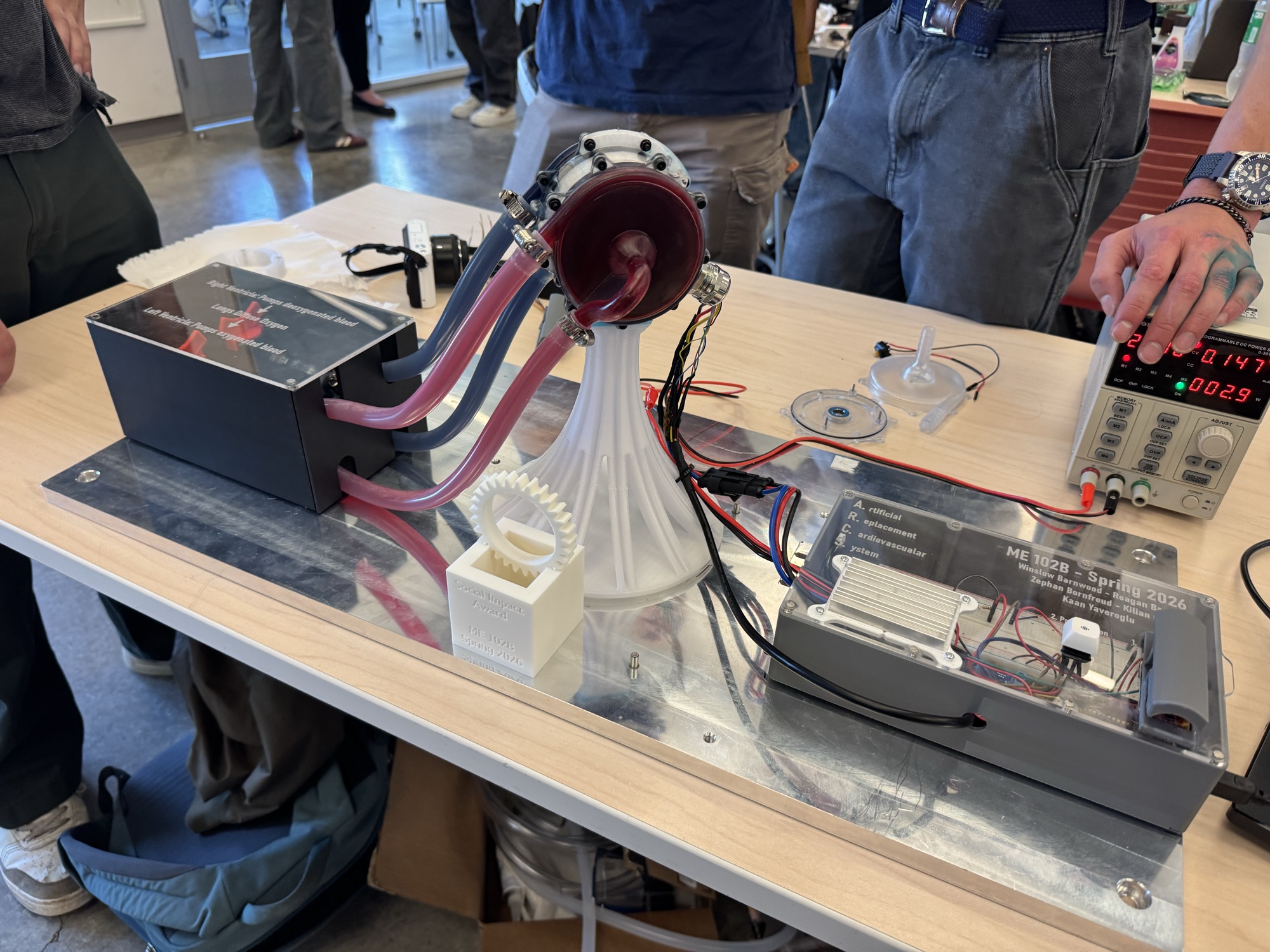
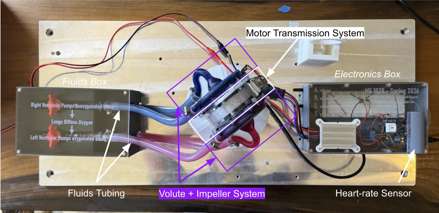
Our project consists of five subsystems. A transmission system in the middle of the heart, a volute & impeller pump system on each end performing as the left and right ventricles, a close-loop tubing system, an electronics box, and a seperate testing rig. The majority of my work focused on the testing rig, the tubing system, display setup, and the volute & impeller pump system.
| Subsystem | Description |
|---|---|
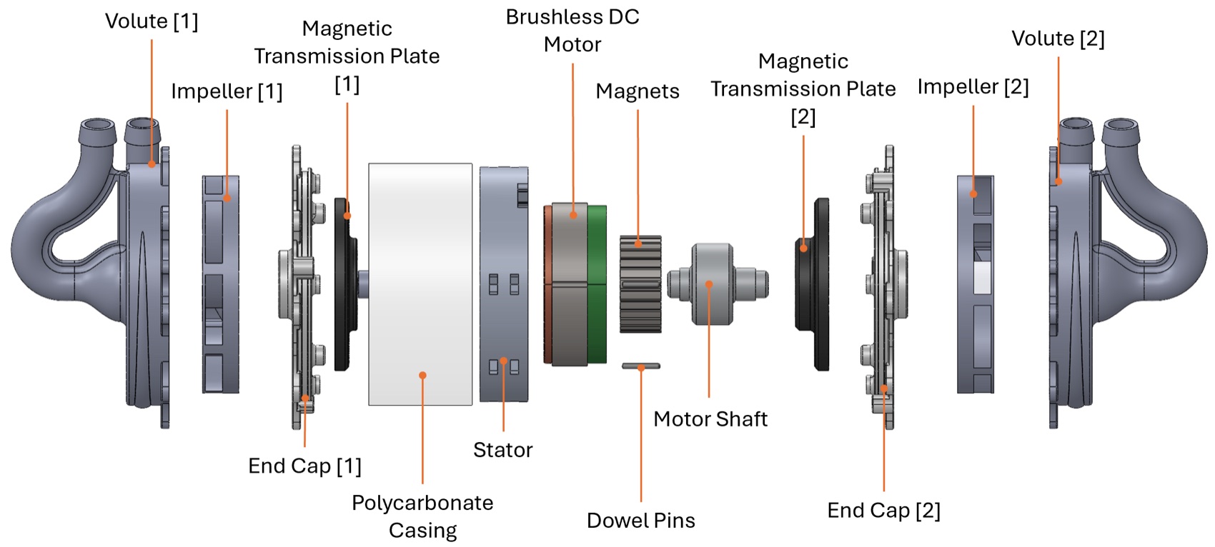
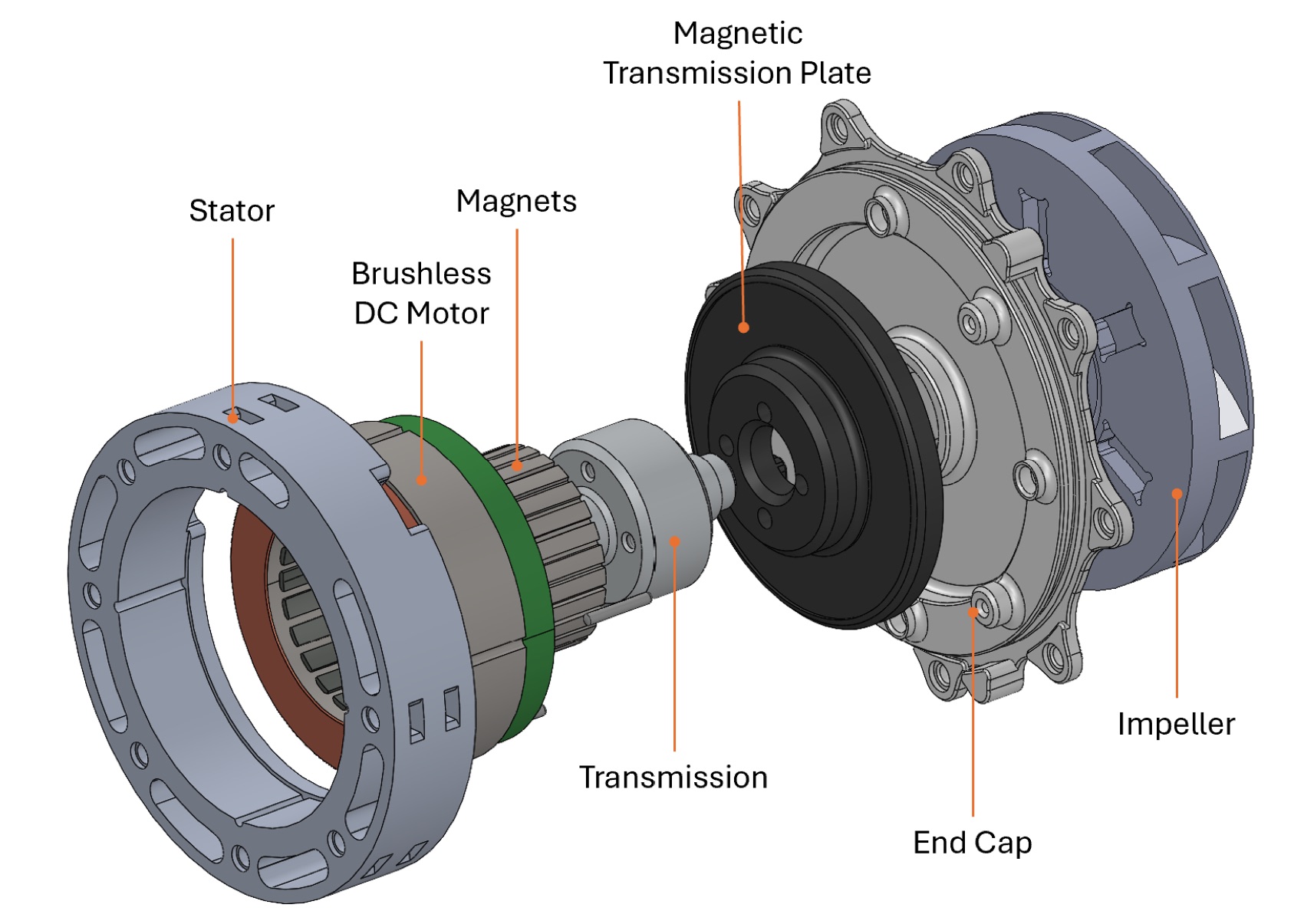
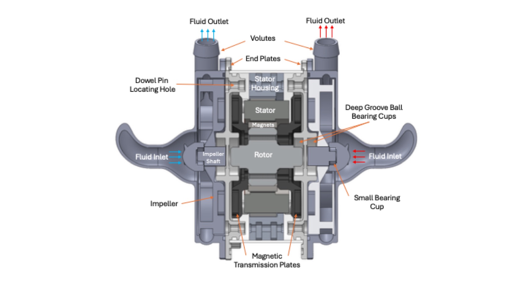
| Motor transmission | Uses a brushless DC Motor with the stator press-fit into housing and a rotor fixed to two magnetic transmission plates. 6 in-line neodymium magnets fixed on the transmission plates and the impellers transmit rotation in a 1:1 gear ratio. |
| Volute + impeller | Inspired by water pumps, the impeller accelerates fluid radially outward, imparting kinetic energy. The Volute surrounds the impeller and converts this kinetic energy into pressure through channels with increasing cross-sectional area. Flow-rate is proportional to impeller RPM. |
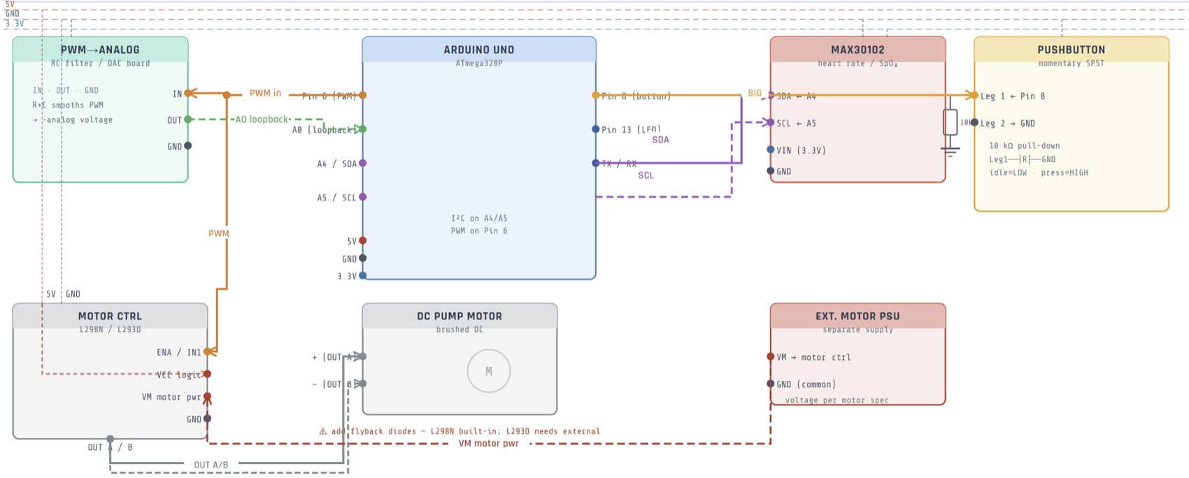
| Electronics box | Houses the Arduino, motor controller, heart-rate sensor, and general wiring. |
| Fluids box | Houses the two closed-loop fluids tubing to circulate the left and right Volute + Impeller system fluid. |
Table 1 · Subsystem breakdown
Test Rig: Design
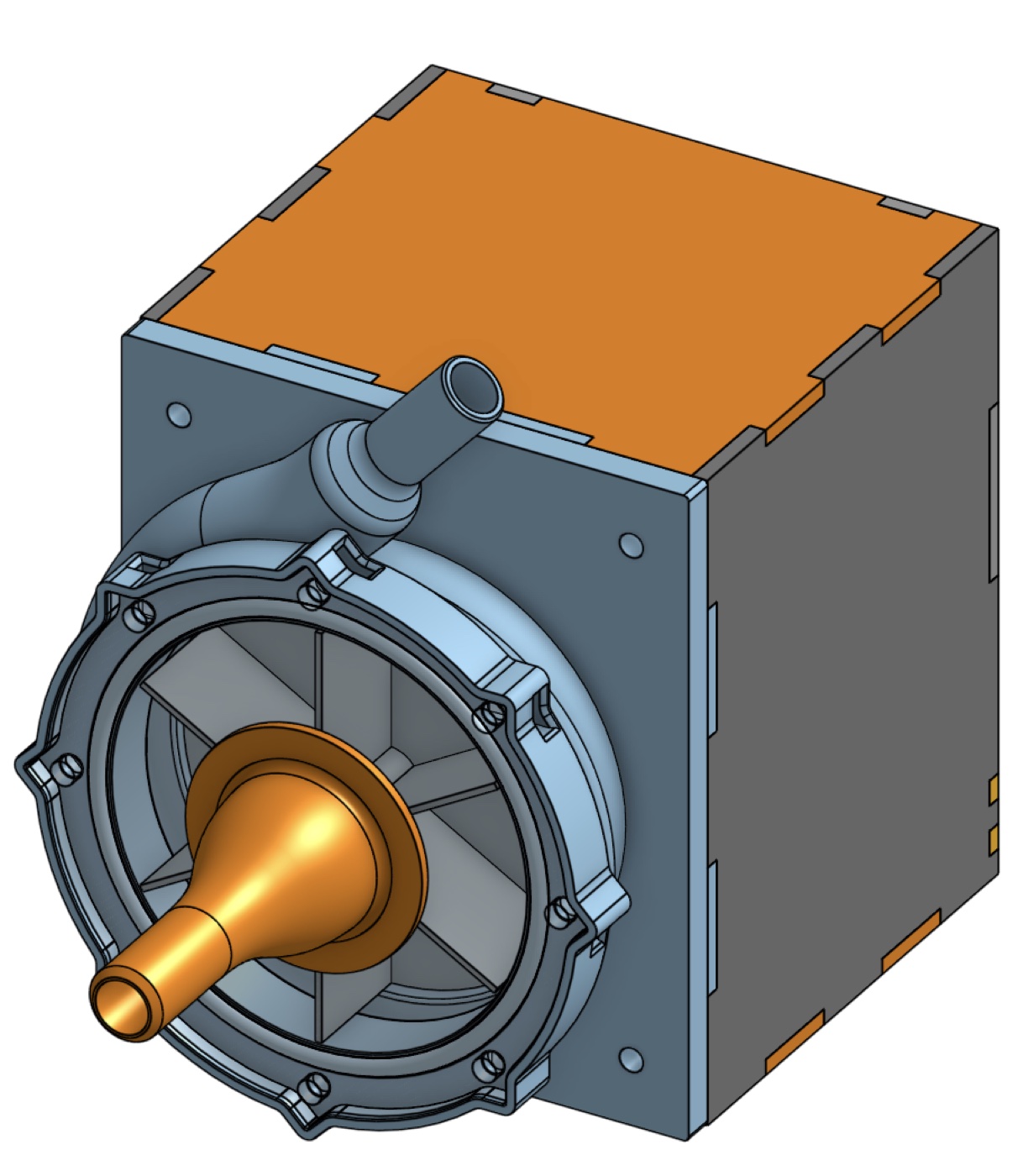

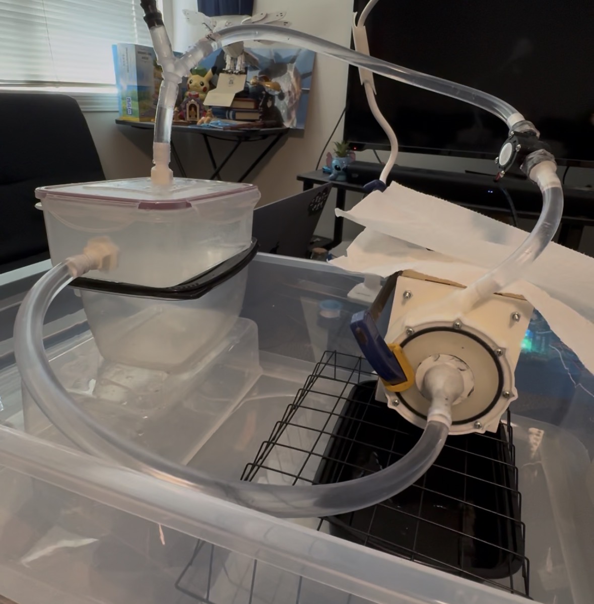
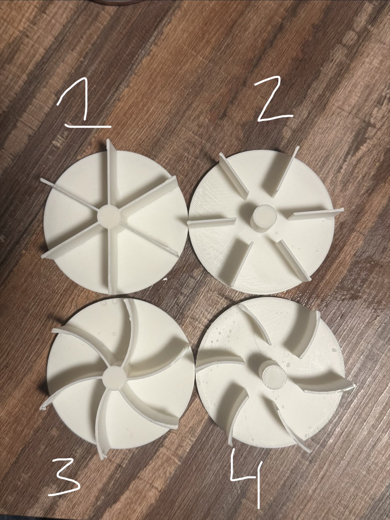
The primary objective for testing was to obtain data on the flow-rate vs. RPM for various impeller and volute designs in parallel with the magnetic transmission bringup. For this, I built a modular test using an electric skateboard motor before the real motor was chosen. I also designed the first iteration of an impeller + volute system inspired by industrial water pumps.
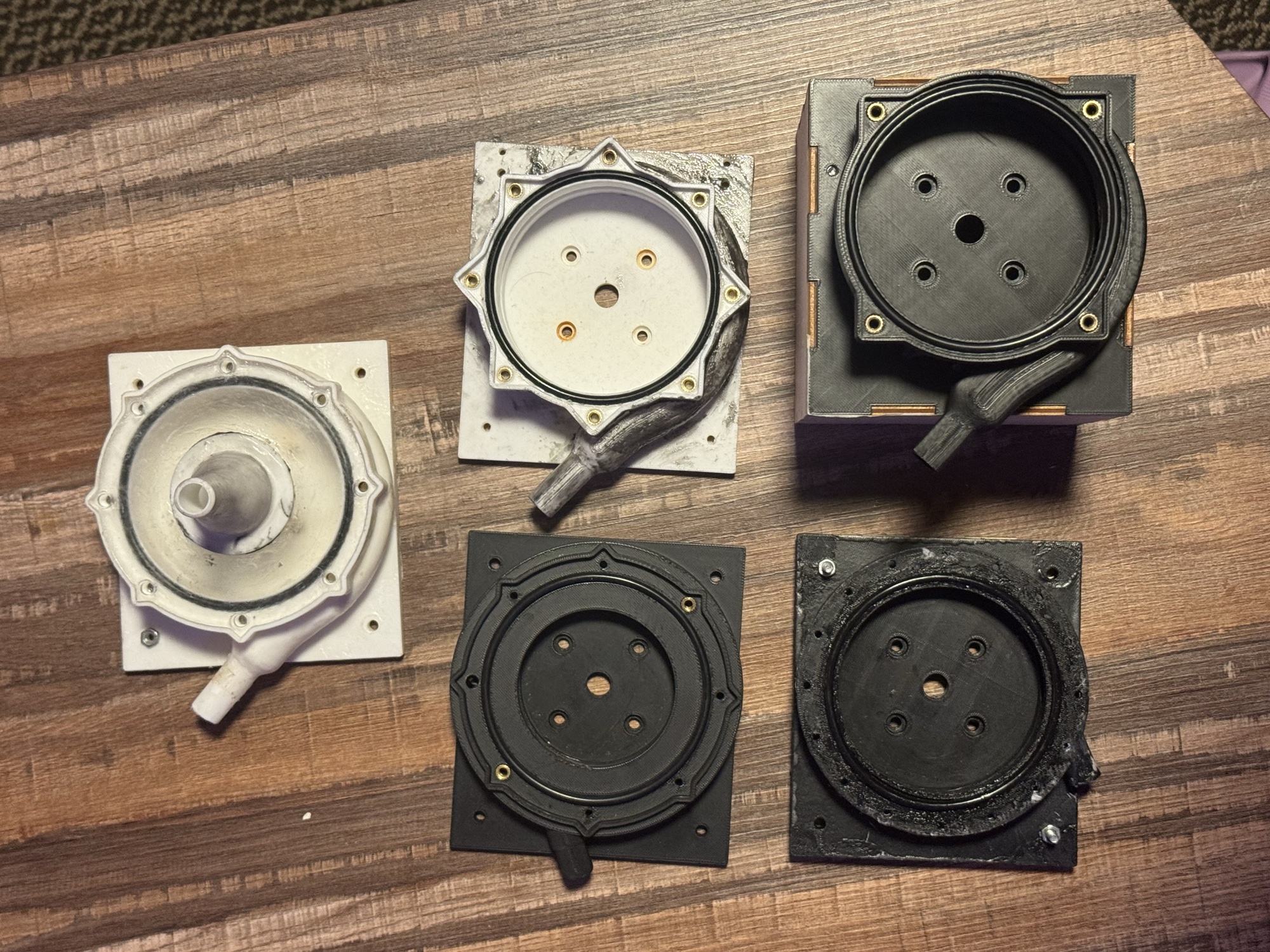
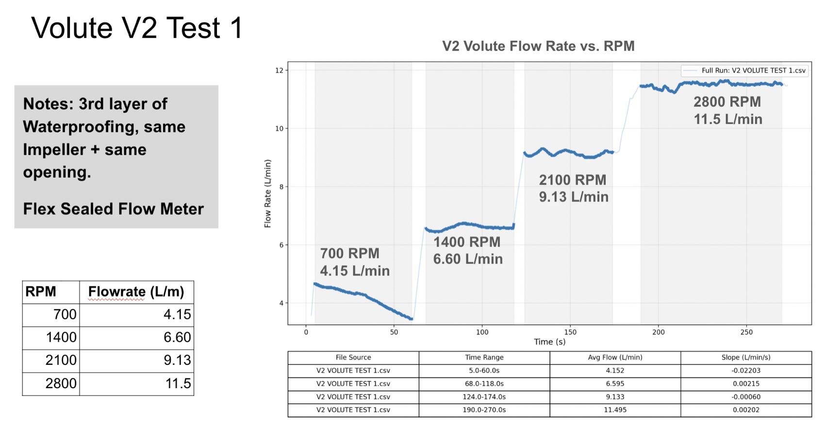
A particularly challenging aspect was sealing and priming the closed-loop system as parts were primarily FDM printed for speed and cost. Flex-seal and orings ended up being my best friend for getting this system working consistently. Multiple volute prototypes were made to improve sealing and pumping performance as seen in Fig. 5.
Test Rig: Process & Results
The process of testing took weeks to hone before obtaining promising results. Through trial and error I learned how to properly prime the pump system, water-proof every part and fitting, and calibrate the flow-meter.
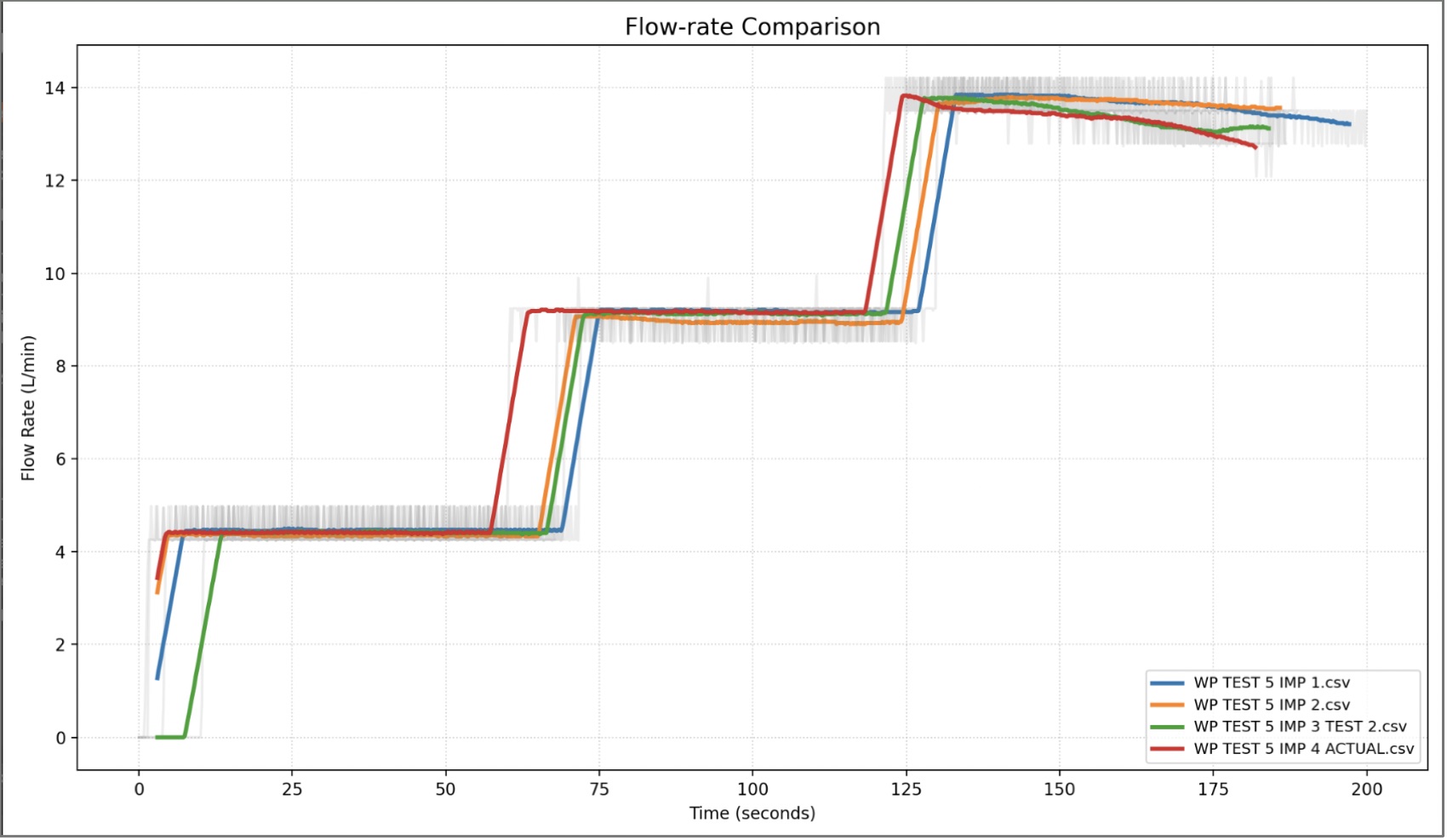
As a result, I obtained key data on the performance of various impeller and volute combinations, and most importantly I identified the optimal RPM to achieve the required flow-rate range. Comparing the data, we can see that there are minimal performance differences (<10%) at the targeted flow-rate.
Functional to Final Prototype
Manufacturing
With the testing rig functional, components selected, and initial designs flushed out, I moved to manufacturing the first fully functional prototype and designing the display setup for our showcase.
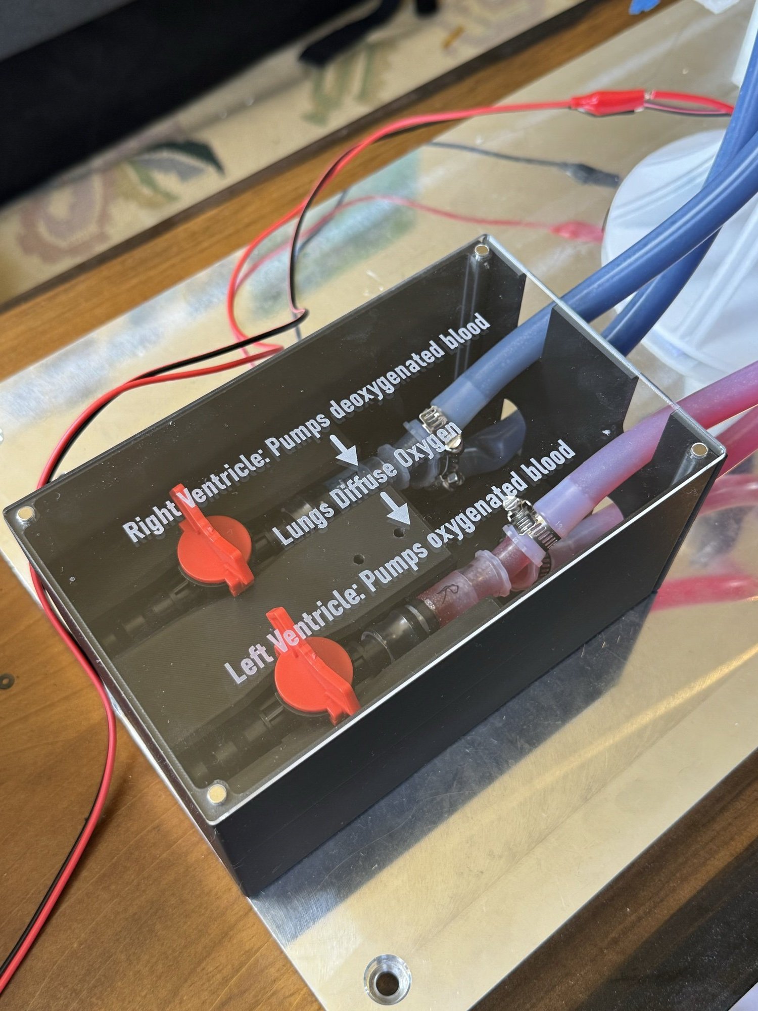
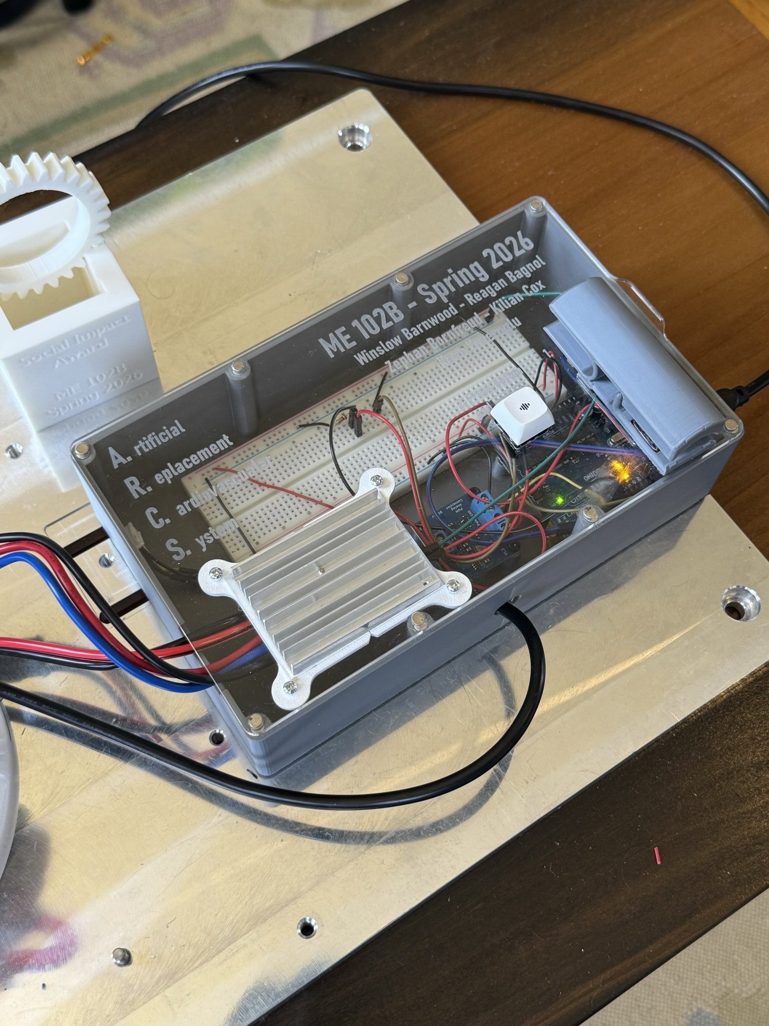
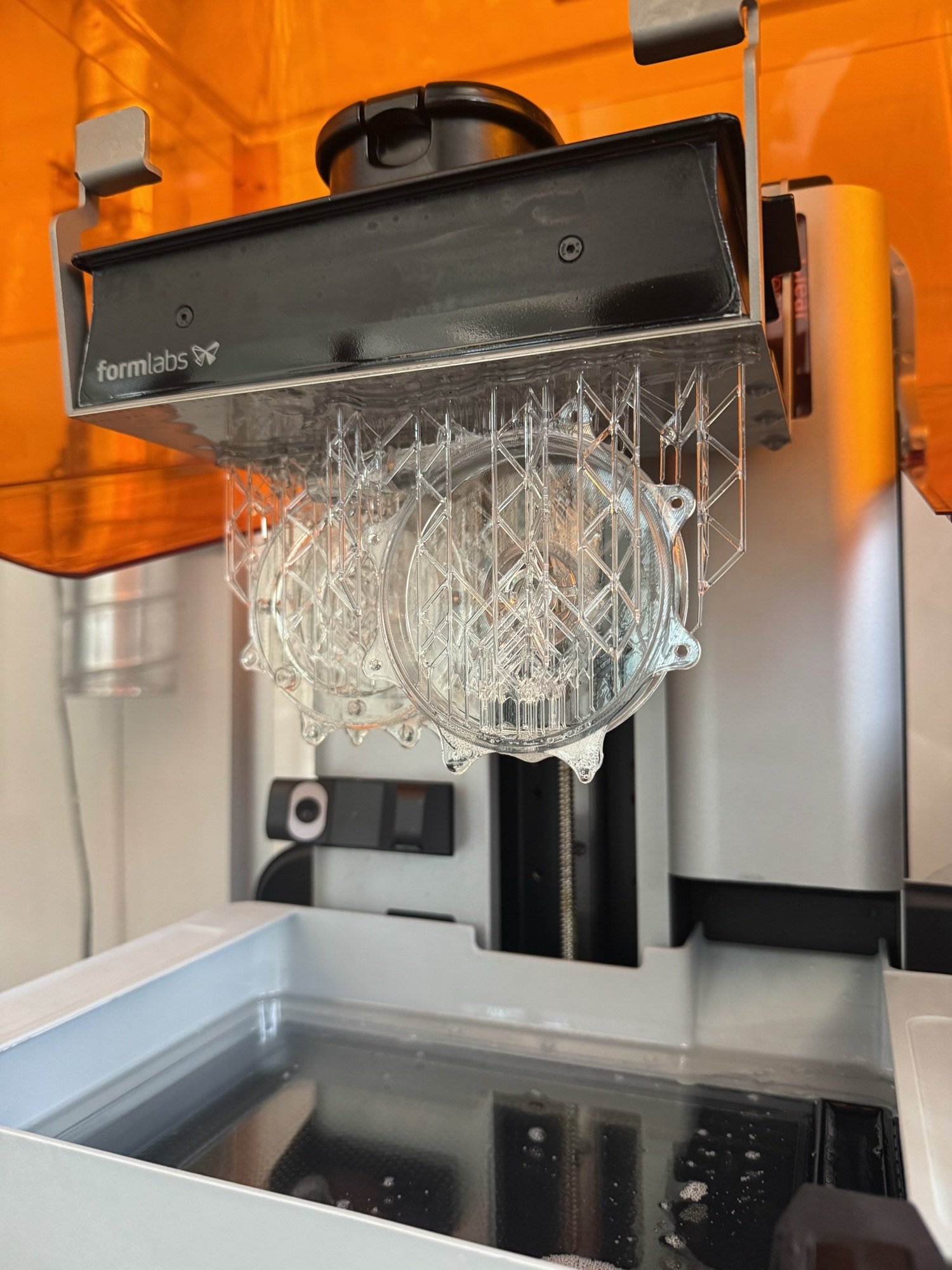
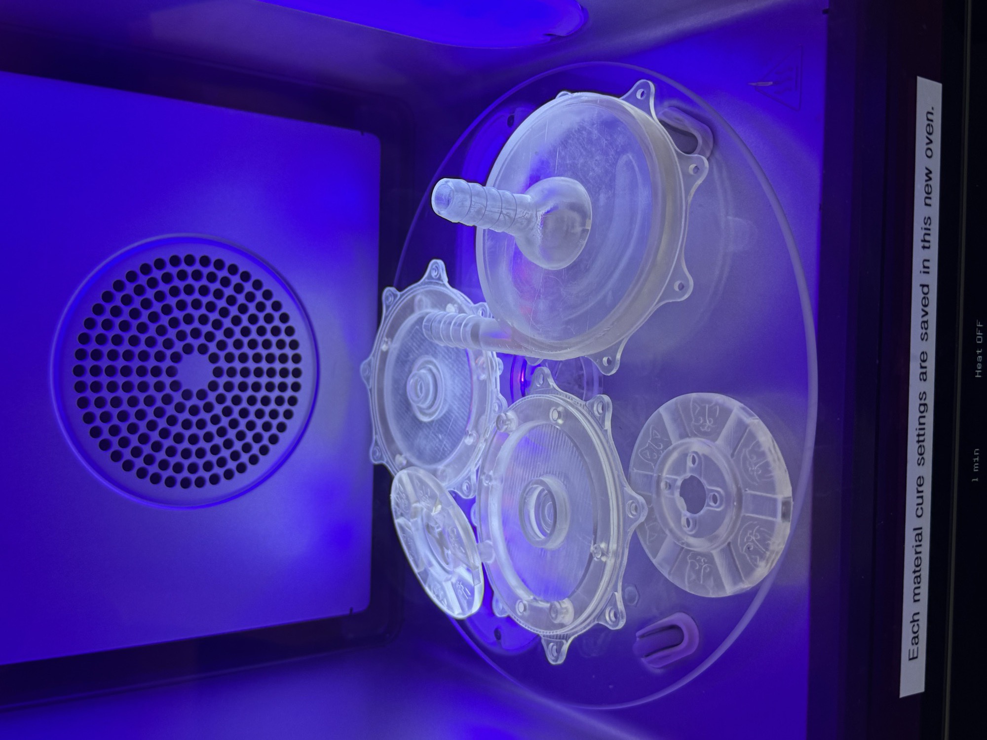
Full Prototype Testing
With the first full protoype made, we verified the flowrate of the system at the target RPM rates and honed the hear-rate sensor and variable flow systems. From Fig. 22, you can see a heart-rate switch from normal (70 BPM) to the recorded 100 BPM by our team member.
Showcase!
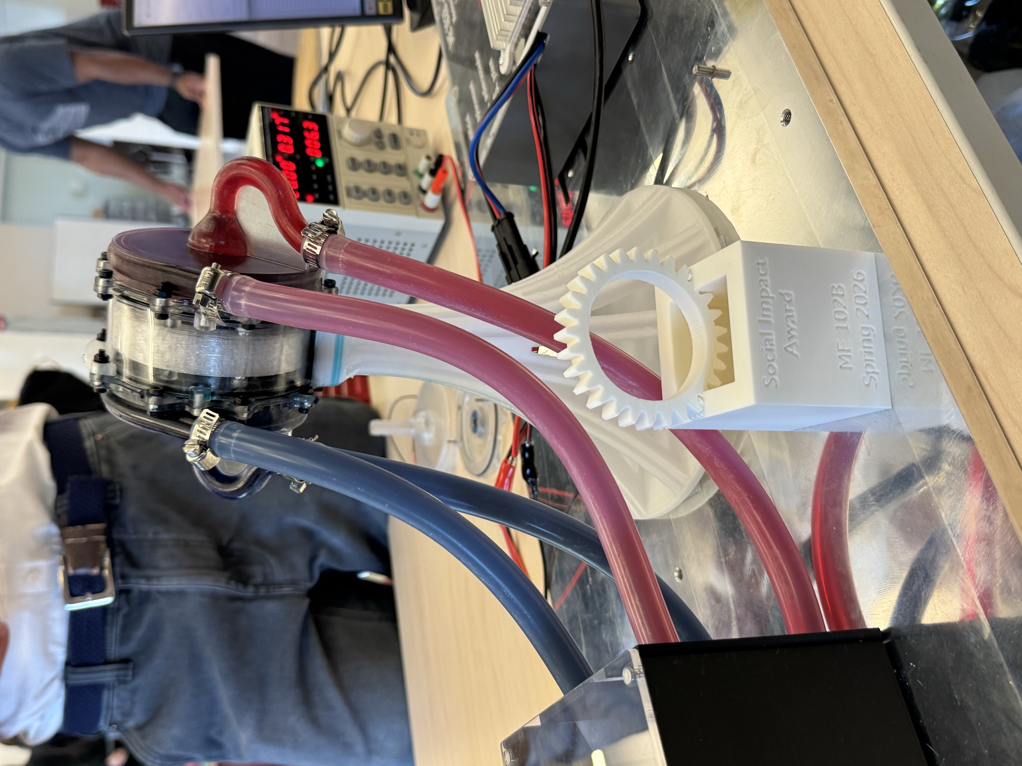
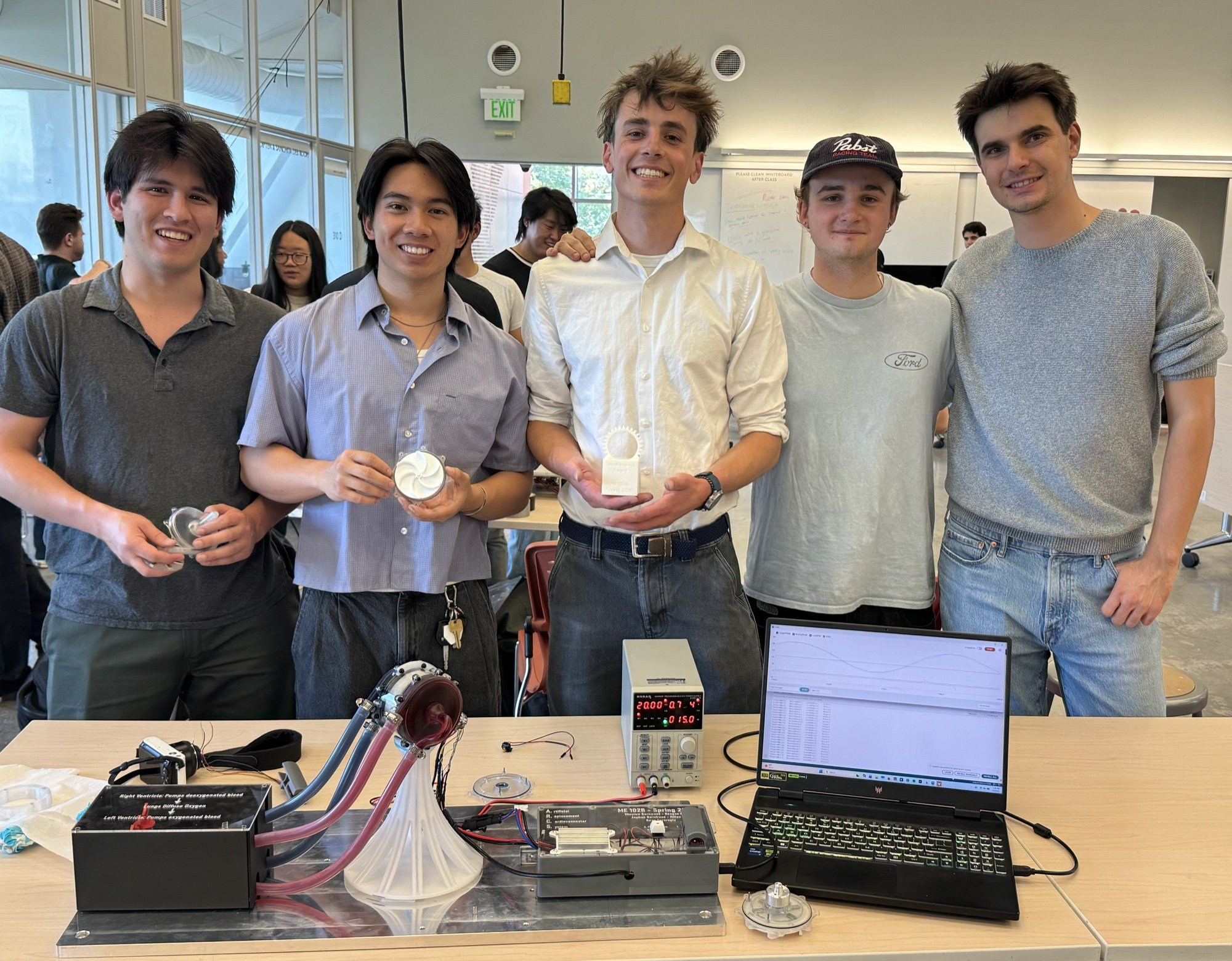
With the system fully functional, we did a final assembly of the Heart with its display parts and presented our work to 100s of Berkeley Engineers, Alumni, and Proffessors. Our work won the "Social Impact" award for an innovative design addressing an issue facing society.
Reflection
This project is the culmination of 4 years of our engineering knowledge cultivated through numerous engineering courses, internships, and passion projects. A project of this scope was daunting at first, and we had many challenges in identifying the right architecture to move forward with and the milestones we had to achieve each week. Properly utilizing every member’s skill-set/time as the semester progressed was the most important aspect of our project’s success, which required daily communication and a deep understanding of our capabilities, garnered through years of working together.
Appendix
Function-Critical Design Decisions
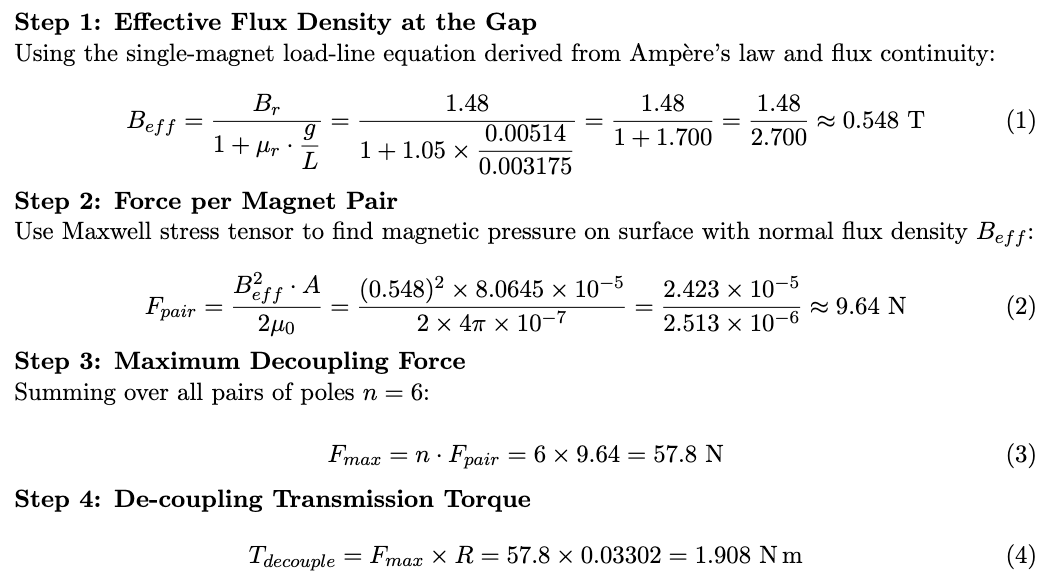
Our most critical components were in the Motor Transmission System, and careful selection was made for the motor, bearings, and magnets, as well as the magnetic transmission design. From my testing of early volute + impeller system prototypes, I identified an RPM of 2500-3000 to reach the target minimum flow rate of 12L/min. From this RPM, as well as packaging design constraints, our motor was chosen for its properties as a 3-phase brushless DC frameless motor with high torque (1.63 N.m) and a max RPM of 5000. From this maximum torque specification, we selected N52 magnets that created a de-coupling force greater than the maximum torque of the Motor: T_decouple = 1.908 N.m > 1.63 N.m
Magnet TS: http://kjmagnetics.com/b842-n52-neodymium-block-magnet?pl=1.2&pf=
For bearing selection, I first found the radial and axial components of the force acting on the bearings. The axial force on the impeller and stator bearings due to magnetic attraction is: n*F_pair = 6 * 9.64 = 57.8N
The radial forces due to weight on the bearings are negligible compared to the radial forces due to mass imbalances of the impeller, concentricity misalignment, and hydraulic forces due to pressure gradients. These forces are difficult to calculate theoretically. Therefore, we selected deep groove ball bearings with a dynamic max load of 1800N to handle both the radial and axial loads of the system with a large factor of safety, and empirically tested the system to determine bearing eligibility. In designing the power transmission, we moved forward with a magnetically driven transmission to prevent the need for a dynamic o-rings to power the impeller. This would significantly reduce the wear in the system and increase the life-span of the Artificial Heart. However, this new system brought up concerns with transmission concentricity and both magnet and bearing retention. Extreme tolerances (+- 0.001in) on the machined rotor and impeller shafts were required to maintain the concentricity between each side of the transmission, as any compliance leads to intense rubbing of internal components. For the 3D printed parts, multiple end plate prototypes were made to create the optimal press-fit for the bearings and improve bearing concentricity. Magnet retention was resolved through epoxying of the magnets instead of a press fit.
Controls
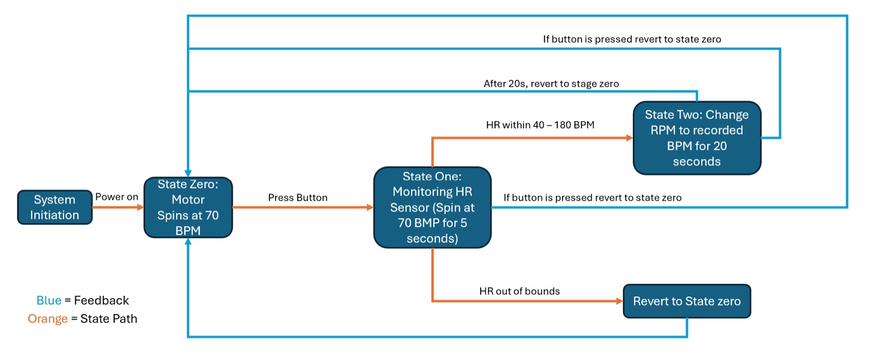
The heart runs off an Arduino Uno with a three-state machine. In steady state, the pump holds a fixed resting rate by writing a sine wave out to the PWM pin. The wave is built off a phase accumulator instead of a delay loop so nothing in the sketch blocks, and the output is clamped between 50 and 225 so the pump never stalls at the bottom of the wave or overshoots at the top.
A debounced button press on pin 8 moves the system into a 5 second stabilizing state while the MAX30102 heart-rate sensor warms up. The pump keeps pulsing at the resting rate through this, and no sensor data is used yet. After that it enters the interactive state, where the frequency of the wave tracks the BPM being read off a finger on the sensor, averaged over 4 samples to keep it from jumping around. It falls back to steady state on a reading outside of 40-180 BPM, after a 20 second timeout, or on a second button press, so the pump is never left chasing bad data. Pin A0 reads the output of the PWM-to-analog converter back into the board, which made it easy to confirm the converter was following the commanded signal while tuning.